Fenrir Rebuild
Since Fenrir was the first robot I worked on (and eventually the first project I led), it holds a special place in my heart. After working on it for a season and working out most of the mechanical problems, I was still unhappy with the state of the robot. Basically, it didn't drive straight!
Historical Design
The concept and initial implementation of Fenrir happened before I came to IIT. It was essentially a project built just to be different. The design is not particularly advantageous for the competition it was ostensibly built for. As power is applied to the drive motors, the whole frame rotates, which makes it difficult for any manipulator mounted on it to stay aligned.
Still, a moving reference frame is not a death knell for robots. With proper sensors, feedback and controls, you could "subtract" out the rotating frame to keep your manipulator level. All you would need is feedback. Which Fenrir had none of.
Fenrir was entirely "Open loop." Propulsion was just telling the motor controllers to send some amount of power to the wheels. Inevitably, this causes one driveline to spin slightly differently than the other, and the robot to veer slightly (or sharply, depending on how different the drivelines were) left or right.
Fenrir's other problem was that the axles were held in by clip rings. A diagram is below:

Fenrir's Axle
In the diagram, the axle is the light gray. Into the body of the robot is to the left, and wheel is mounted on the larger stepped diameter. The blue box is the block that restrains the shaft from moving axially into the robot. The yellow box is a thrust bearing (later a Delrin bushing after the bearings got eaten. The black box is a normal bearing, able to bear radial loads. The darker gray box is an angular contact bearing, resisting radial and the axial forces that would pull the shaft out of the robot. However, the axial force is transmitted to the angular contact bearing entirely through a single clip ring (red)!
This clip ring would fail, the axle would unseat from the thrust bearing and the radial bearing, and the shaft would slip the chain, crippling the robot. At first, it was thought that the clip ring slots were just poorly machined into the shaft, but even with new shafts machined, the problem still occurred.
Therefore, my first senior year improvement to Fenrir was to replace that clip ring with a screw in shaft collar. It was created by boring some black steel pipe to the correct internal diameter, then drilling and threading 1/4-20 holes. A photo is below.
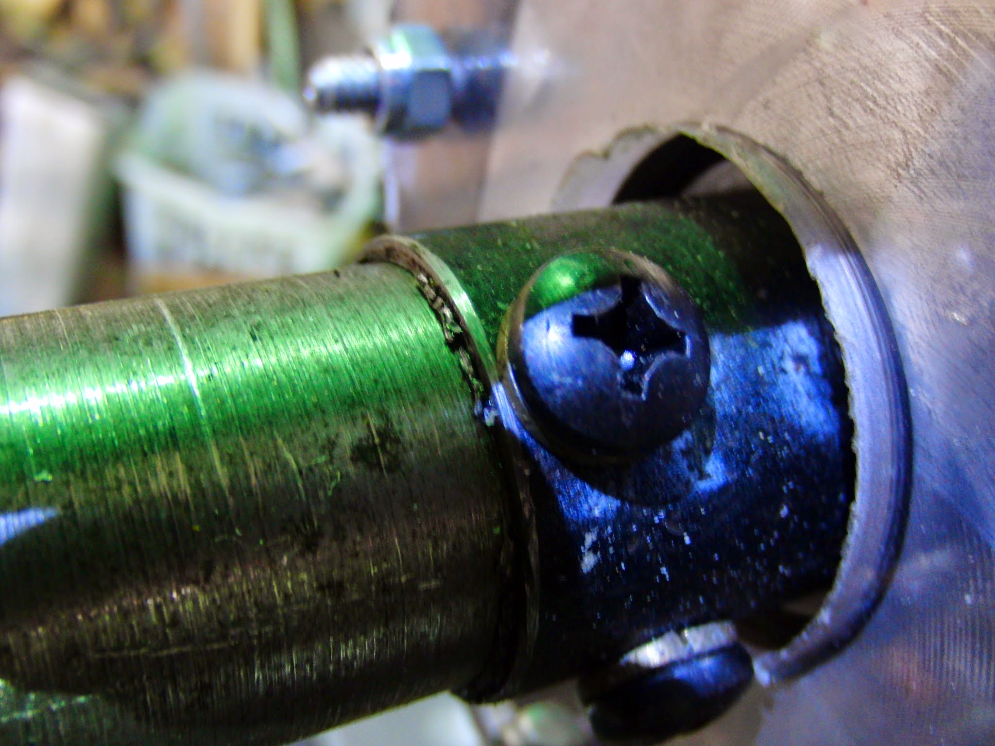
Fenrir's New Shaft Collars
The second, more involved, fix was completely rebuilding Fenrir's electrical and control systems. In the year I was not involved with the project, the new caretakers had ripped out or trashed all of the electronics work I had done, so I stripped out all the remaining wiring and started fresh.
The target of the rebuild was to introduce speed feedback and control. This was done by creating what I termed "speed servos," independent controllers on each wheel connected to the motor controllers with feedback through quadrature encoders. Communication to the controllers is through i2c, and accepts inputs for the P, I, and D terms for the controller, and of course the target speed. In order to tune the controller, recorded speed can be returned from the controller. The controller P, I and D tunings are saved and loaded from EEPROM. The code for the speedservos can be found on GitHub.
One of the other members of the team decided that he wanted to use C to control the robots, instead of the Java controller code we were using before. That code is also on GitHub. Significant work was done cosmetically and on the robot side to adapt it to controlling Fenrir. Those changes can be found on the Fenrir branch. The most obvious modification is that the code now has a pretty ncurses front end!

Oooh, ncurses!